الوصف
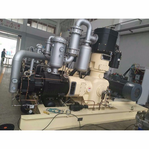
The PET air compressor is the main body in the air blower of the blow molding machine. It is a device that converts the mechanical energy of the prime mover (usually an electric motor) into gas pressure energy. It is a special blower for compressed air. Air pressure generating device. Blowing air compressors are divided into: low pressure blowing machine (15-25bar), medium pressure blowing machine (25-35bar), high pressure blowing machine (35-40bar).
main pump structure features
Compression series: three-stage compression, one stage is double-acting cylinder, and second and third stage is single-acting cylinder.
Long journey: 10% to 30% or more longer than the same industry.
The piston force is small: the stroke is long, the piston diameter is reduced, and the piston force is reduced.
Low exhaust temperature, three-stage exhaust temperature of 90 ° C ~ 130 ° C, greatly extending the life of consumables.
Number of piston rings: 1 to 3 rings per stage, reducing leakage per stage and reducing useless work.
Minimal vibration: Accurate weight control of moving parts for dynamic balancing.
Each stage has a high efficiency cooler that allows the compression cycle to approach isothermal compression, reducing power loss.
Machine configuration features
The whole machine adopts "L" type design, long stroke and simple structure. The main components are installed on one frame, which overcomes the shortcomings of "V" and "W" type strokes and complicated structure. There are two crosshead assemblies, two connecting rods and bearings, and the third stage has no piston rod packing, which is more conducive to the sealing of the third stage high pressure gas, and also solves the shortcomings of the high pressure grade packing of the horizontal opposed compressor. The smallest moving parts, the second and third stages are smaller and placed horizontally to maximize piston ring life.
All components are installed on the same base, including air, water and emptying interfaces. No special foundation is required, the installation cost is low, simple, and the maintenance is convenient and fast.
The whole machine adopts PLC control. The temperature, pressure and pressure of the first, second and third stages are all sensors. The oil pressure and water path are also equipped with sensors. The signals are controlled centrally by the PLC, and there are automatic fault alarms, over-limit shutdown, and multi-unit automatic operation. Joint control.
Each stage has a safety valve in addition to the pressure sensor, and a three-stage high-pressure pressure sensor, an ultra-high pressure alarm pressure switch and a three-layer protection measure for the safety valve.
The oil cooler and the automatic oil pump reserve a lubricating oil heating interface on the fuselage, which can be configured according to customer requirements (optional).
The water cooling system is equipped with a booster pump to ensure the amount of cooling water required by the unit.

|
S/N |
ITEMS |
TECHNICAL DATA |
|
|
1 |
Working medium |
OIL FREE AIR |
|
|
2 |
model |
LW-12.4/70 |
|
|
3 |
Structure |
oil free reciprocating,L type Two line |
|
|
4 |
Pressure stage |
4 |
|
|
5 |
Rated capacity(standard)Nm3/h |
680 |
|
|
6 |
Rated inlet pressure MPa(G) |
Atmosphere pressure |
|
|
7 |
Rated outlet pressure MPa(G) |
7.0 |
|
|
8 |
Inlet temperature℃ |
≤30 |
|
|
|
Pressure of each stage |
2.2/7.8/26.3/70 |
|
|
|
Discharge temperature of each stage |
145/139/151/131 |
|
|
9 |
Outlet temperature ℃ |
≤= |
|
|
10 |
Transmit gas temperature℃ |
≤45 (after cooling ) |
|
|
11 |
Shaft speed r/min |
460 ※ |
|
|
12 |
Cooling way |
Water cooling |
|
|
13 |
Lubricate way |
Shaft and connect rod |
Lubricate oil |
|
Cylinder |
Oil free lubricate |
||
|
|
Shaft power |
≤145kw |
|
|
14 |
Motor power Kw |
160KW ※ |
|
|
15 |
Transmit way |
Belt driven |
|
|
16 |
Installation way |
Simple basement |
|
|
17 |
Automatic control parts |
Overload ,stop automatic |
|
|
18 |
External dimension L×W×H mm
|
4650*2200*2780mm ※ |
|
|
19 |
Gas Inlet and outlet mm |
|
|
|
20 |
Weight Kg |
8000KG ※ |
|
|
21 |
Voltage |
380 /50 /3 phase |
|
|
22 |
Water consumption |
|
|
|
23 |
Water inlet and outlet mm |
|
|
|
24 |
Pressure for each stage barg |
2.2/7.8/26.3/70 |
|


